Cotton Gin NIR Robot
Disclaimer: _The views and opinions expressed in this article are those of the authors and do not necessarily reflect the official policy or position of any agency of the U.S. government. Examples of analysis performed within this article are only examples. They should not be utilized in real-world analytic products as they are based only on very limited and dated open source information. Assumptions made within the analysis are not reflective of the position of any U.S. government entity. _
Introduction
This was meant at one point to turn into a publication aimed at HardwareX Open-Source Hardware Journal to cover the hardware end of the research, in order to complement another publication to a cotton journal which covered the science end. My internship eventually came to an end as did the fruitions of bothering to publish this but the information is still nice and I worked hard on the project so here it is in the form I had left it in 03/2018.
Abstract
A modular and low cost two axis articulating robot for automating manually controlled laboratory and field instruments against test articles in-situ. The robot, which is also denoted "Lenny", uses common hardware, extruded aluminum channel, and hobbyist grade motor and control systems. The system is modular in that the probe end can accommodate many handheld laboratory devices, and the system can be assembled in any Cartesian coordinate configuration given that common CNC controls are easily configurable to any range of applications. The caveats in use of low cost components and expedient deployment are addressed with many application notes regarding improvements. The robotic system described here has its performance applied in a commercial cotton gin over two harvest seasons, with improvements applied over the second season. In this environment the robot is subjected to harsh vibrations and impact, heavy dust contamination, and Louisiana summer and winter weather conditions.
Hardware in Context
Introduction
The ability for a researcher to have access to a low cost and modular means of collecting samples is valuable especially when that tool is able to accommodate an array of instruments which would be otherwise relegated to handheld use. With robotic sampling automation come the benefits of linear pressure application, time precise repeatability, decreased labor costs, and 24/7 operation.
Many laboratory and field instruments which may or may not accommodate automation do have interfaces which can accommodate serial or USB connection to a PC or microcomputer which can perform triggering and logging of samples. However proprietary these instruments may be, with the use of macros to automate their OEM software or the sniffing of their respective serial protocol, most instruments can be easily controlled remotely and triggered by a widely configurable set of inputs.
With the recent surge in 3D printing and hobbyist CNC offerings there are many systems currently available which can be repurposed towards use in automating instrument use. The cost of hardware development in non-critical instrument automation systems has greatly widened in range to accommodate many low cost offerings which can perform adequately in harsh environments if the design heeds particular foresight to components which may not be sufficiently rugged. Some extra attention paid in specifying hobbyist equipment for ruggedized environments result in cost savings of as much as half or a third the price of equivalent proprietary motion and control
Instrument Application
Use Case Context
The hardware application this system was developed for was for use in researching the near-infrared (NIR) spectroscopic measurement of cotton fiber properties in-situ. Cotton is one of the most important crops in the United States. The US Department of Agriculture classes every bale of cotton produced in the country for key attributes including micronaire. Micronaire, a measurement of cotton fiber fineness and maturity, is typically measured via mass-compression and air permeability.
NIR spectroscopy has been employed to indirectly measure micronaire by way of density of hydrogen bonds within the cotton fiber with over 97% accuracy in laboratory testing. This trial was to ascertain the feasibility of deploying these measurements and modeling outside the laboratory.
Cotton warehouses do not have testing data to help organize bales when they arrive, resulting in randomly arranged bales that require additional time and energy of multiple bale movements to assemble shipments. Additional bale movements increase labor and energy costs as well as the chance of damage to the bale and potential for contamination.
Cotton fiber property measurements taken in-situ at the gin could allow for warehouses to organize bales according to fiber properties, hence value, before receiving official classing data from the USDA classing offices.
Cotton Gins themselves could also benefit from the availability of a preliminary micronaire measurement as a tool to assess how they can better handle the cotton as it is being ginned based upon its fiber characteristics.
The data taken in these trials will be modeled against the official USDA classing data for cotton fiber properties of each corresponding cotton bale. A model with correction factor for consideration of conditions will be established for laboratory micronaire readings to NIR in-situ measurements.
Industry adoption of this technique could support US agriculture by curtailing logistical costs and product degradation. Further publication with greater scope and depth into measuring these fiber properties in the gin environment are to follow as they fall outside the scope of this publication.
The modularity of this system allows the accommodation of most handheld sensor probes, thus in addition to adding a colorimetric sensor in the second trial year this system is able to be deployed in many different configurations for future studies.
Needs of the Automated Measurement System
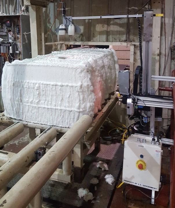
A system which articulates an NIR spectrophotometer is utilized in a commercial cotton gin for the 2016 season, with the addition of a colorimetric spectrophotometer in the 2017 season. The system must withstand the rigorous environment of a cotton gin which exposes instruments to heavy dust, outdoor temperature conditions of Louisiana summer and winter seasons, vibrations, and impacts which are significantly different than the laboratory environments in which previous NIR research has been conducted. Readings take place on the cotton bale weigh table following the bale press.
The robotic apparatus should be additionally resilient to collision with cotton bales in the case of mechanical failure or cotton bale strap failures, which were both seen in the 2016 season, with improvements made to mitigate this risk in 2017 season. Readings are required to be conducted in a window of 7-45 seconds depending upon deployed gin location.
USDA Agricultural Marketing Service standard Permanent Bale Identification tags with Code 128 barcodes containing corresponding 12-digit bale identification are also logged with a barcode scanner to link each bale sampled to its classing data. The system should accommodate use by a technician of a broad range of technical abilities and be suitable for reconfiguration to meet the needs of a variety of missions. Control systems and motion paths should be able to be reconfigured with layman's knowledge of the systems. The system should be capable of recovering from power loss without operator input. The system should allow remote off-site access of all instrument, motion, and control systems, and redundant storage and backup of instrument sample data.
Platform Selection Concept
The platform was designed based on the specifications of having instruments placement in an industrial cotton gin, the research goals of the instrument, the initial goal of getting from idea to field deployment in two weeks, and a low budget relative to existing apparatus.
These constraints beget an instrument based on a unique use case of a modular use platform utilizing CNC controls and hardware from the wide affordable selection available at
OpenBuilds Part Store. OpenBuilds Part Store is a hardware supplier which distributes low-cost hardware components for hobbyist grade machining, whose proprietary hardware designs, assemblies, and models are distributed as open source.
Competing quotes for prebuilt linear actuators and control hardware found were not competitive and had lead times exceeding the goal of collecting data that harvest season. Furthermore, we found that a large portion of distributers offering a completely custom suite of hobbyist tier hardware were redistributing from OpenBuilds. Thus the majority of hardware components needed to build this robot is available from OpenBuilds. Other hardware used was obtained from McMaster-Carr, DigiKey, Amazon, or bench stock on hand.
Hardware Description
Mechanical Hardware
Movable Axes
This assembly has two axes of linear motion and one axis of rotation. The vertical Y axis and horizontal Z axis use linear actuators and the rotational X axis for mitigation of collisions with sample material.
Base Mechatronic Platform
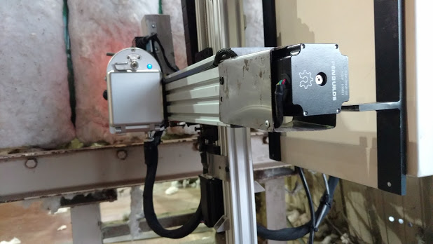
OpenBuilds C-Beam Linear Actuator Bundles serve as the basic platform the robot was built upon. The 1000mm C-Beam bundle served as a Y-axis for vertical motion and 500mm for Z-axis horizontal bale probing motion. Double Wide C-Beam Gantry Plates which accommodated eight wheels were supplemented in place of the four wheel Gantry Plates for additional shear force resilience. A NEMA 23 1.26Nm stepper motor (MT-2303HS280AW-OB) was utilized in the Z-axis and a NEMA 23 2.44Nm high torque stepper motor (MT-2315HS300AW-OB) in the Y-axis.
Modifications
Impact Resilience Hinge
Due to an equipment failure in 2016 version, a
Bommer single acting spring hinge was affixed between the Z/Y gantry to mitigate damage due to collision with cotton bales coming down the conveyor belt in the case of automation failure or failed cotton bale straps. The spring hinge chosen was highly efficacious in mitigating damage
by being able to swing the Z axis instrument arm in the X direction then return home. The hinge pressure is also adjustable, so the hinge did not cause any inadvertent X axis sway.
Timing Belt Drive
The 2016 power transmission configuration used the C-Beam Linear Actuator Bundle acme lead screw drive configuration that was included in the bundle. 2017 revisions changed Z-axis drive to a belt driven configuration which utilizes a polyurethane HTD 5M 15mm width, 14T drive pulley, and 16T idler pulley. The drive system moves the Z-axis with belt ends static mounted to the dual gantry plate carriage. This configuration was selected out of a large shortcoming in the 2016 configuration being both speed and multiple lead screw coupler failings. Consequentially with the belt driven Z-axis, sans instrument reading time a complete motion circuit with the desired four measurement points on the bale could be made in 4 seconds in belt drive versus 15 seconds in lead screw drive. The addition of speed allowed us to tune 12 NIR readings points to each bale with still ample additional time overhead.
This belt style drive configuration is not an explicitly noted configuration from OpenBuilds, and uses larger drive belts than the GT2-3M belt configuration they offer. No belt tensioning pulley or torsion spring was found to be necessary given the robots seasonal use and the large reinforced belt specified.
Hardware
Wheels
The polycarbonate wheels that OpenBuilds recommends for heavy use and includes in the C-Beam kit degraded over time and disintegrated in chunks after many cycles. The recommended white lithium lubricant was used and the wheels were not over-tightened. After finding additional anecdotal evidence of other users suffering similar degradation and communication with OpenBuilds it was found that we may have received a bad batch of wheels. OpenBuilds volunteered full replacement of the wheels and was happy to oblige in our opting for Delrin wheels. They sent two sets of each Delrin and Polycarbonate Mini-V Wheel Kits. The delrin wheels performed exceptionally well through the 2017 harvest season as well as around 1500 test cycles before deployment. The replacement polycarbonate wheels were not tested.
The bearings would also fail and seize or grind from brinelling or fatigue. We opted to replace the bearings that OpenBuilds includes with something better and found that a large gap exists between cheap and quality, with quality Japanese, American, or German made 5x10x4mm bearings ranging $5 and up per bearings at local supply houses and online, and cheap bearings around $1 each. We opted for some cheap ABEC 3 bearings which we'd hoped were at least better than the OpenBuilds bearings that we experienced as well as others on their forums and purchased MR-105-2RS-BU from TRB RC. Since then no bearings have yet to require replacement. Anecdotally bearing failure among OpenBuilds users appears to be consistent only in long term continuous use cases.
Dust Shielding
A dust shield was fabricated from sheet metal for use in covering the unused upper half of the lead screw drive in the Y-Axis. The shield was found to serve the additional benefit of holding the lead screw from bowing out of the linear rail during a mechanical failure which stopped the carriage from moving vertically.
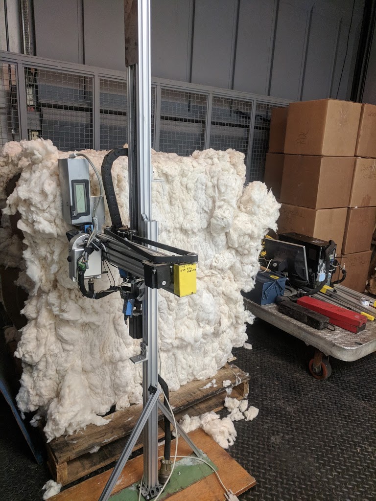
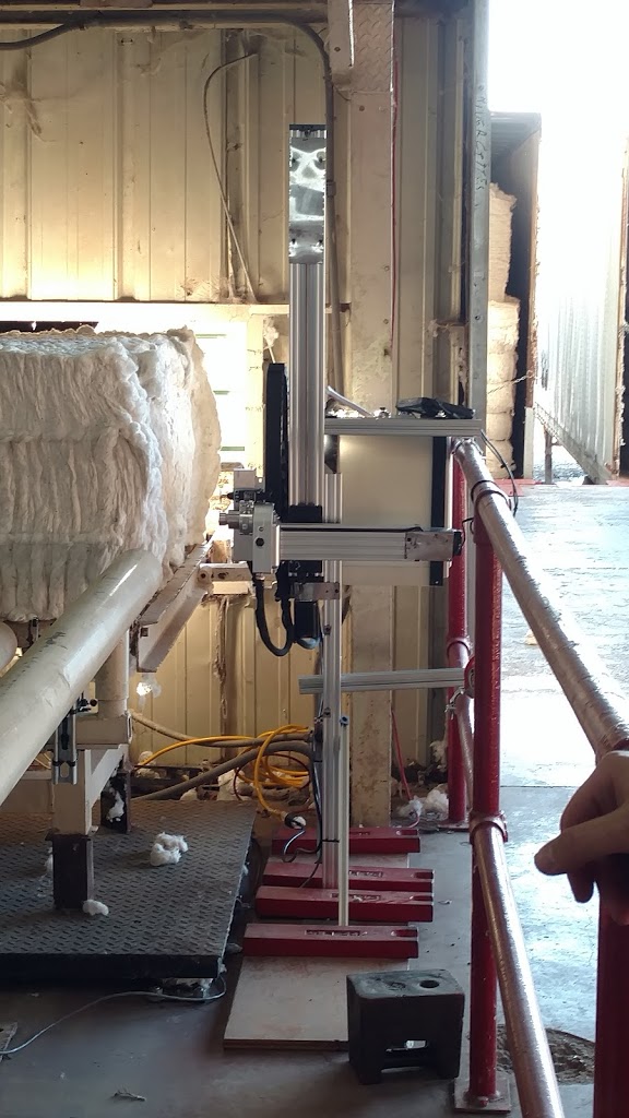
Mounting and Base
The Y-axis C-Beam assembly was mounted to a 1000mm V-Slot 40x40 linear rail with two cross joining plates to form a vertical structure from the base. Two 500mm 20x20 linear rails served as support arms mounted in 45 degree orientations from the vertical structure to the base foundation. The structure mounts to a base steel plate which is mounted to a larger wooden base. Four 25lb weights were placed on the base to ballast the robot in place without adding mounting hardware to the gin's concrete floor. Two 40x40 rails were mounted horizontally to the vertical structure and clamped to the adjoined preexisting safety hand rail with 2 inch O-Clamps
Electrical System
Housing
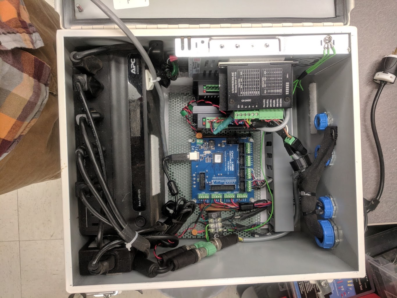
A Hoffman A14128CH 14x12x8" IP65 industrial control system housing was modified for use. This unit scavenged from textile processing equipment was of adequate rigidity, included fittings and mounting, and adequate dimensions for accommodating all control systems, power, and UPS backup power.
Power Distribution
AC
125VAC line input power was provided from the cotton gin. An APC BE425M Back-UPS 425VA Uninterruptible Power Supply (UPS) is used for surge protection and to keep control systems active during power interruptions. This UPS was sized for and found to be sufficient to provide a weekends power all control systems, instruments, and the Panasonic ToughPad FZ-G1 used in 2016. In 2017 with the move to a desktop PC and additional peripherals added, this UPS was found to provide backup power for 20 minutes at best before cutoff. AC power is provided via outlets on the UPS to the PC, DC PSU, and Viavi PAT-W PSU.
DC
A 24VDC 350W Meanwell SE-350-24 Power Supply is used to power the stepper motor drivers and control board. The control board steps this 24VDC down to 5VDC via an onboard power regulator. Input power draw to the stepper drivers is at maximum 160W.
Stepper Drive Systems
Two Wantai DQ542MA 2-phase hybrid stepper motor drivers are used, one for each axis. The axis are configured via onboard dip switches, which will vary per application in current and microstepping. Attention should be paid to proper chassis grounding methods, noise mitigation, and isolation from control systems as observed with this particular driver despite its onboard optically isolated signal I/O.
Connectors and Cabling
Strain and Chafe Relief
Wires for motion and control of the robot in the primary cable bundle are fed through heat shrinkable 25mm nylon braided cable sleeve. 18mm*50mm drag chain is used to feed cables through to the Z-axis, to accommodate Y-axis vertical motion. A measure to reduce strain at cable bend points is taken with either heat shrink or gaffer tape. Chafing contact with moving components and especially near pinch points is taken with careful cable length sizing and securing cables to the machine with cable ties and mounts. Some smaller cables can be pressed into the channels of the extruded aluminum and secured in place with gaffer tape or with OpenBuilds Slot Cover.
Connectors
For modular use and simplified setup and teardown, inline connectors were added to all cables. 3-pin XLR type connectors were used for trigger switch cables. A MIL-DTL-5015 specification 37 pole Cannon plug connector was used inline in the primary cable bundle.
Wires
The cabling and wiring used includes primarily high quality on-hand scrap procured from German industrial textile machines which include sizes 12AWG/4 shielded, 20AWG/4, 14AWG/6 shielded, 24AWG/8 shielded, as well as 22AWG solid and stranded copper hook-up wire.
Where applicable, shielding throughout the cable was single-point bonded to a common ground rail inside the enclosure at the source and left unbonded at the destination on the other side of the cable with prevention of ground loops in mind as per the norm.
Shielding and Electromagnetic Interference (EMI)
Stepper driver signal wire noise sampled at the control board via oscilloscope while the motors were enabled reflected noise which was reduced. Better planning for shielding or separation between the cabling for the stepper motors and the signal wiring would have resulted in a moderate decrease in EMI resulting from inductive coupling which was otherwise accomplished with ferrite toroids and capacitive decoupling.
Mitigation of line noise and EMI was accomplished through use of 22mm ferrite toroid cores and 7mm clip-on ferrite ring cores, with attention paid to any long signal wires, control system power inputs, and the control board USB cable.
A common point of intermittent issues with hobby grade controllers and CNC boards which are controlled via USB is noise on the USB cable causing the computer to drop the connection.
Control System
CNC Controller
A CNC controller board was used in order to keep costs low relative to most PLC based control systems;a PlanetCNC CNC USB Controller MK3/4 4 axis stepper controller was used. PlanetCNC CNC USB TNG Beta Controller software was used. The board was found to be stable, and the software was reliable. In the first year build, an API was not available and the ability to insert instructions such as triggering program loads or emergency stops was limited to predefined commands which would be executed in the application's MDI input. The primary limitation of this application was a limited implementation of probing cycles. The probing that was available was not able to be customized and it was limited in use. The TNG beta version of the software later found provided access to the underlying implementation of many of the G-code functions as well as a robust API and configurable control of every button and setting in the software from G-code or shortcut input.
Stepper Controller Board I/O
Drivers
Stepper drive is accomplished through use of two Wantai DQ542MA Stepper Motor Drivers. One of these drivers suffered intermittent failures in the second season and was replaced. These drivers induced a large amount of line noise when the stepper motors were enabled.
Ferrite toroid cores were marginally successful at isolating this noise. A higher quality stepper motor driver such as those from Geckodrive would serve as a recommended upgrade.
Limit and Triggering Switches
At the cotton gin used, in the location of the instrument the cotton bales are located at an indeterminate distance to within a 100mm margin on a weigh table after a conveyor belt pushes the bale in place to be weighed. The challenge exists in that typically when using a CNC, material will typically be loaded to within a tight margin of ranges and probing is needed sparingly when setting up axis offsets. This application required multiple probing cycles per bale in order to measure four points on the bale because of the oblong bale shape and margin in which it was placed on the table. Probing against a limit switch was needed with each reading to ensure a uniform pressure against the instrument aperture regardless of position and shape.
The simplest viable solution found within the limited assembly time was to drive the CNC controller forward a definite amount of steps in excess of that required, interrupting pulses to the driver when the Z axis limit switch was triggered, and allowing the CNC controller to continue to send pulses which would not be received by the driver. When the direction was reversed at the end of the determined length, which was determined with excess to allow sufficient time for the instrument to take readings, the Z axis was homed to reset the machine axis position since in the absence of a stepper encoder the position was unknown after driver pulses were interrupted.
Microcontroller Piggybacking
In the first build, the application of an Arduino UNO R3 microcontroller which takes Z axis limit switch input where bale contact is made. The microcontroller interrupts logic level pulsed inputs to the stepper driver by pulling the pulse input from the CNC controller to ground. Pulsed inputs to the driver are allowed to resume by reading the direction pin logic level input to the stepper driver. When a direction reversal was detected, the microcontroller would disengage grounding of the pulsed input which would allow the motor to home the axis. A limit switch placed at axis Z- position allowed the CNC controller to find home position.
Another caveat for control of the PlanetCNC CNC USB software in the first build was that external inputs could not trigger the start of a cycle. The simplest viable solution found within the limited assembly time from parts on-hand was to have an external limit switch placed on the bale conveyor input to an Adafruit Trinket 5V microcontroller, which was connected to the computer
In the 2017 build, the PlanetCNC TNG beta software, a full API and numerous additional methods of running custom cycles and code were made which were sufficient to write a probing method and a limit switch behavior profile sufficient for this unique use case. This version of the software reduced reliance on batch scripts and AutoHotKey, and more reliable communication with the software was made available through API calls directly to the software rather than AutoHotKey feeding keystrokes into the MDI input.
Instrument Triggering
The Viavi PAT-W Spectrophotometer did not natively support triggering via a hard-wired signal wire. The provided configurations supported tilt triggering via its integrated 6DOF sensor, timed triggering via the tethered software, manual triggering via the tethered software, pushbutton input via the instrument, or presence sensing via a provided passive IR trigger. Binder brand connector # 99-0487-12-08 was needed in order to add a custom digital trigger to tie into the CNC controller for software controlled NIR sampling without having to modify the accessories loaned by Viavi.
The Konica Minolta CM-2600d colorimetric spectrophotometer triggering was accomplished through use of onboard 'Remote' mode and serial communication to PC with their control software triggering readings and logging to Excel. An AutoHotKey macro script was used to allow the CNC control software to trigger the instrument control software.
Data Logging
Viavi PAT-W NIR Spectrophotometer
The PAT-W NIR Spectrophotometer provided by Viavi was used in the recommended configuration in the 2016 build. The OEM Viavi PAT v1.0 software was used and with a WiFi tethered connection to the PC the data was acquired via triggering outputs coded into the G-Code and output by the CNC controller. Though in the event of power or connection loss the PAT-W sensor could backlog readings independently of the tethered connection to the software, the software could not be closed by the user without it sending a "kill" signal to the ongoing sampling. Thus natively the software tethering was required. Intermittent connection drops and eventually a persistent failure to connect which was later found to be a bug with the software's implementation of Bonjour protocol caused us to need to send the instrument and PC to Viavi for troubleshooting. We were warned that at that time the PAT software was to be considered "still in beta." Timestamps weren't available in the readings from PAT v1.0 so reliance on tagging data to bales was made through logging of file creation timestamps for each reading.
In the 2017 build, the Viavi SDK was requested and found to be very useful for bypassing the reliance on a tethered connection to the PAT software. With this we were able to extract the raw NIR readings for post-processing, timestamp data which was not supported in the PAT software, instrument temperature, and we could control the instrument directly instead of setting it up with the PAT v1.0 software. Separately from the SDK and on the instrument side, since the instrument uses a BeagleBone Black microcontroller running embedded Linux with U-Boot and BusyBox, root access to U-Boot bootloader, calling of the PAT-W instrument control service processes, and root filesystem access was made possible by an FTDI cable to the BeagleBone TTL serial debug port and root access was acquired via a password reset made possible by running a stock BeagleBone image from SD card, SSH access through the debug port, mounting the eMMC flash image, and changing password. This allowed for remote SSH access to the instrument to perform command line reboots, instrument initialization, confirmation of malfunctions via monitoring the PATService from the Linux 'top' command, and FTP access to the file structure which allowed backups of the NIR samples to be taken. In the unique use case which we had an entire day's drive to perform any troubleshooting or fix malfunctions, the concentration on remote access meant this capability saved a lot of work. There were two instances where commands to the instrument via the software, APK, or the PAT Diagnostic software via Bonjour or direct IP were not working but direct SSH access to reboot the instrument served to remedy the fault. The raw NIR samples taken via this method also allowed for us to have timestamped samples. It was found in post-processing that there was a drift in the instrument real-time clock. It appears that the time is only synchronized with the PC time via the initialization of the instrument through the PAT software, and whether or not the PAT software remained tethered the timestamp drift occurred. Only initialization of the sampling process would sync the clock. Once this was discovered and replicated, samples from 2016 which could not be reliably timestamp tagged to bales from 2016 were then able to be identified as well.
After a post-ginning season debriefing with Viavi, they provided a newer version of the PAT software and their implementation with Open Platform Communications (OPC) process control. Viavi affirmed that most bugs we experienced were solved or were being solved, the PAT software is more stable, and the OPC integration is more robust and reliable. Further testing will be done to integrate this new platform for the 2018 ginning season.
Konica Minolta CM-2600d Colorimetric Spectrophotometer
In the 2017 build a handheld Konica Minolta CM-2600d was added to the existing apparatus. This instrument was salvaged from a lab having been out of use for some years, and was not designed for standalone applications. Given the modularity of the mounting plate being a simple piece of L-shaped aluminum channel, the PAT-W and limit switch were mounted lower to accommodate the CM-2600d. An enclosure for the instrument was fashioned from scrap galvanized 16 gauge sheet metal. Communication with the instrument was accomplished via the PC onboard serial port. The CM-2600d Accessory Software which was meant for manual operation was controlled via a signal received from the CNC control software triggering an AutoHotKey script which sends a pseudo click on the 'Measure' button. The Accessory Software logs its reading and timestamp to Excel.
Barcode Scanning
Reading the Bale Tags is critical for matching the bales to the instrument samples. Timestamping the arrival of each bale to the unique identifier on the tag allows the sampled data to be compared to official USDA classing office data in post-processing. Two HHP IT3900 barcode scanners salvaged from on-hand lab instruments were connected via Serial-to-USB cables and interfaced with ExtraPuTTY software which supports timestamped serial data logging. The barcode scanners were suspended above where the bales pass via an aluminum outrigger affixed to the Y-axis C-beam. Two barcode scanners were used to widen the usable range. Design reliance on the ginning staff to place the bale tag in the correct orientation and location consistently was not high. Thus through the combination of infrequent barcode scans and a consistent bale arrival and sample interval, the missing bales could be deduced in post-processing. The use of a wider aperture Presentation style omnidirectional laser or CCD barcode scanner would have proved beneficial.
Video Recording
Two Logitech C615 webcams were affixed at two points in the gin to aid in remote troubleshooting and to aid in reducing ambiguity with lining up the sample data in post-processing. One webcam was placed ~3 meters from the instrument for a wide-angle view and the other was placed above the barcode scanners with both the instrument Z axis movement and the bale barcodes in view, as a backup to the barcode scanners. The webcams were managed in OBS webcam internet livestreaming software. OBS was chosen because the initial plan was to maintain a 24/7 YouTube livestream as well as a backup to an onboard 2TB storage drive. This software was also simple to add timestamps and screen recording to the stream and recording. The livestream was eschewed when it was found that the gin's internet throughput averaged 1.5Mbps at best, and given that connecting to the computer via TeamViewer and viewing the OBS software proved to be very reliable it was not necessary. However the majority of video recordings from the recovered instrument proved to be corrupt and unrecoverable for an unknown reason. The FLV file format was used for recording for its ability to not become corrupt in crashes and power loss, though this did not prove to be the reality in our case. In retrospect the use of purpose built webcam surveillance recording software would be recommended. OBS does not break recordings into segments, so a bi-daily remote login and OBS recording Stop/Start was performed to reduce the sizes of the individual recordings.
A Note on Data Logging and Timestamps
Good planning for redundancy and backup at all levels of a design is critical to success, especially in the rollout of a limited use autonomous and remotely placed instrument such as in our use case. Testing for every possible failure mode can prove crucial to saving months of data. In the case of our 2016 build, hardware failures and insufficient bale tagging challenged the post-processing data lineup. In the 2017 build, the discovery of most video log files being corrupt, the eventual discovery of the PAT-W RTC timestamp drift, power losses during gin shutdowns, and the inconsistent barcode readings amounted to a similarly challenging post-processing data lineup. Alas, the amount of redundancies that were in place did allow for very reliable data-lineup given the design gave heed to the foresight that there were so many uncontrollable variables in the work environment. It behooves the designer of an apparatus which requires strict data integrity to invest as much mental labor in testing for failures as they do in designing for robustness.
Interface and Computing
PC Hardware
In the 2016 build a Toughpad FZ-G1 provided by Viavi with the PAT-W instrument and running Windows 8.1 build 6.3.9600 was used. In 2017 an on-hand salvaged Dell OptiPlex 7010 workstation PC running Windows 10 v.1709 build 16229.19 was used. The switch to the full-size PC was made to accommodate the additional I/O ports and processing power needed given the addition of more instruments and the webcams. The switch to a higher consumption PC did greatly reduce the time of autonomy of the UPS backup, which dropped from adequate to survive a weekend gin shutdown to lasting 20 minutes.
Remote Cloud Storage
Microsoft OneDrive was tied to the folder which contained any available real-time logged data. Frequent backup and retrieval of all instrument data remotely via TeamViewer was also performed.
Operating Systems
BIOS and Operating System Setup
Given the unpredictable operating environment and reliance on autonomy and remote access, the system required it boot into a ready state for remote access and with the instrument Z axis being out of harm's way upon restore from power loss. In the PC BIOS, restore on AC/power loss settings were configured to boot the computer back up after a power loss.
Windows Caveats
Forced Updates
Windows 10 has a heavily persistent system of forced updates; despite recent revisions claiming otherwise. All Windows updates, extraneous services, and potentially disrupting processes were disabled. O&O ShutUp10 was found to be highly useful in disabling most of the offending processes.
User Account Control (UAC)
To simplify the restoration of system operation upon power loss, to include automatic login, and simplified ability for batch script and AutoHotKey ability to execute processes with administrative rights, UAC was disabled. Retaining the security convenience of UAC had necessitated numerous caveats and loopholes, thus at a certain point the disabling of UAC and concentration on firewall and port control security at the router proved simpler. Given the security risk of disabling UAC in Windows, it is advised that if a build is operated with connection to the internet for an extended time that precaution should be taken to avoid malware or unauthorized access.
Windows Subsystem for Linux
Bash on Windows was very helpful with simplifying SSH interface with the PAT-W instrument and was a viable compromise to not using a fully Linux build. Unfortunately the primary interfacing software for both spectrophotometers were Windows only and Wine compatibility proved to be unreliable.
AutoHotKey
AutoHotKey scripts proved instrumental for simple integration of the instruments to the control software, and for automated recovery of the computer. Upon recovering from power-loss, the PC was able to automate opening all scripts, control, instrument, and remote access software, and restore to a complete ready state.
An AutoHotKey script was also used to perform triggering on the Konica Minolta color spectrophotometer's control software via background pseudo-clicks. This software had otherwise no other API access or DLL level external control.
Hardware Conclusion
Initial selection of a hardware and software platform for automation of the instruments in this project underwent a relatively low level of vetting. This project was not born out of a flagship goal of the research unit thus had a relatively low budget. The initial hardware selection and purchasing was completed over the course of two days, and the first iteration of the robot was operational two weeks later. Given the conditions that the design and build of this robot stems primarily from one part time engineering student, this apparatus can serve as a platform for inspiration to future builds for the work of others in the Open Source research realm, whether to provide context of what to do, or what not to do. Our timeline was imposed against the deadline of going from idea to field implementation in time to gather enough samples for a 2016 seasonal cotton harvest dataset, as production in the collaborating cotton gin shut down mid-November until the next year. Numerous challenges and issues were inherently addressed in real-time with a range of elegance balanced against utility. The 2017 season revisions were greatly a result of failures and caveats observed in the rugged gin environment.
Alternative Configuration
Other Controllers
In a 2017 version 2 iteration, a PMDX Model PMDX-416 SmartBOB-OptoUSB motion controller with firmware rev 0.52.254 was paired with Mach4 2.0.3481 CNC control software. In this attempt, Mach4 was found to be restricted in use. The user is restricted to Lua scripts which can only perform software interface within the bounds of Mach4 defined variables and custom variables which can manipulate these variables. Hardware plugin customization and access to variables such as axis location are restricted in the software without use of an SDK restricted for hardware developers only. Through many days of research and coding, and the support of Mach Support and the online forums, numerous limitations could not be resolved which would allow use of Mach4 outside a strictly predefined sandbox. Mach software does however remain a terrific solution for use in dedicated CNC machinery. The SmartBOB motion controller also suffered intermittent connection drops from PC which were only recoverable from when the drivers were reloaded or the board was reconnected. A ferrite toroid core installed on the USB cable at the USB-A side was recommended but did not prove effective, and oscilloscope inspection of the line did not reveal a great deal of noise.
In hindsight, use of an entry-level PLC based motion solution such as those offered from AutomationDirect could have provided a system of higher reliance. The use of a microcontroller based motion control such as Arduino was a viable solution as well but would not have afforded modularity and layman's operation. The use of a control board typically relegated to 3D printing could also work very well. We found that while all these solutions work great in concept, the addition of a long probing depth of indeterminate length is outside the sandbox of most CNC and 3D printer software and will need to accommodate workarounds or a custom implementation altogether.
Computing and Software
Linux Viability
If at all possible, it would be recommended to utilize a completely Linux-based system. In the interest of reliability, security, ease of use, being open-source, and essentially "doing exactly what you tell it to do," most Linux builds consistently prove far more reliable and caters well to custom instrument builds over other operating systems. Some builders may have a simple enough system or a system of such dedicated use that it may behoove them to use a System on Chip (SoC) Microcontroller such as a Raspberry Pi or BeagleBone. These microcontrollers have the additional benefit of on-board GPIO communication and inherently great support for sensor and motion I/O. The designer may want to consider the processing power required for their build, or may even consider an SoC microcontroller as a subsystem since the difficulty of linking the microcontroller to a primary PC via SSH or similar protocol can be made trivial with modern supplementary software.
Design Files
Code: github.com/rellimmot/Lenny_Cotton_Robot
Bill of Materials
This bill of materials is listed as the assembly was built in its final form. This bill of materials includes parts from on-hand scrap, denoted with ~. Parts from kits are listed beneath the kit and denoted with #. Parts obtained from kits but not used are not listed. Hardware which was used to upgrade failed hardware are italicized. Materials associated with wiring the actual instruments used are omitted given the system modularity. Items purchased in bulk are noted as such, which skews total costs as an economy of scale.
Bill of Materials: Lenny_BOM_032618.xlsx
Build Instructions
Since the mechanical assembly consists mostly of parts adapted from extruded aluminum channel and brackets obtained from OpenBuilds, a majority of the assembly falls in line with those offered by OpenBuilds. The deviations from a standard OpenBuilds build will be detailed herein. Consideration should be taken with any fasteners which will need to be exceptionally tight or will need to be removed and reinstalled more than once. The fasteners provided by OpenBuilds are not recommended because their hex caps strip extremely easy. Identical specification fasteners of a stronger grade purchased from McMaster-Carr performed far better.
*Cough* the build instructions section is still missing…